
Page 86 - Сигурност и отбрана - брой 2 - 2024
P. 86
Сигурност и отбрана, брой 2, 2024 г. Научно списание
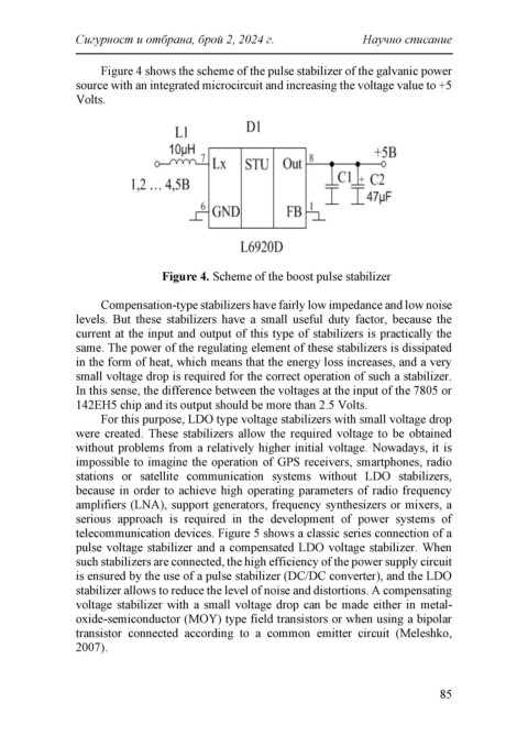
Figure 4 shows the scheme of the pulse stabilizer of the galvanic power
source with an integrated microcircuit and increasing the voltage value to +5
Volts.
Figure 4. Scheme of the boost pulse stabilizer
Compensation-type stabilizers have fairly low impedance and low noise
levels. But these stabilizers have a small useful duty factor, because the
current at the input and output of this type of stabilizers is practically the
same. The power of the regulating element of these stabilizers is dissipated
in the form of heat, which means that the energy loss increases, and a very
small voltage drop is required for the correct operation of such a stabilizer.
In this sense, the difference between the voltages at the input of the 7805 or
142ЕН5 chip and its output should be more than 2.5 Volts.
For this purpose, LDO type voltage stabilizers with small voltage drop
were created. These stabilizers allow the required voltage to be obtained
without problems from a relatively higher initial voltage. Nowadays, it is
impossible to imagine the operation of GPS receivers, smartphones, radio
stations or satellite communication systems without LDO stabilizers,
because in order to achieve high operating parameters of radio frequency
amplifiers (LNA), support generators, frequency synthesizers or mixers, a
serious approach is required in the development of power systems of
telecommunication devices. Figure 5 shows a classic series connection of a
pulse voltage stabilizer and a compensated LDO voltage stabilizer. When
such stabilizers are connected, the high efficiency of the power supply circuit
is ensured by the use of a pulse stabilizer (DC/DC converter), and the LDO
stabilizer allows to reduce the level of noise and distortions. A compensating
voltage stabilizer with a small voltage drop can be made either in metal-
oxide-semiconductor (MOY) type field transistors or when using a bipolar
transistor connected according to a common emitter circuit (Meleshko,
2007).
85